Waypoints
Introduction
Waypoints are the graphical symbols that show up on the
Timetrack Panel. Each time the value of a parameter is
edited in Animate Editing Mode, a Waypoint
will be created. For example, when you adjust a Tangent
Handle of a vertex in a Spline <https://en.wikipedia.org/wiki/Spline_(mathematics)>, a Waypoint
will be created to note the change. However, you didn’t really adjust
the tangent, you adjusted the two parameters which define the tangent:
its angle (Theta), and its length (Radius). Opening up the
tangent’s nodes in the Parameters Panel will show
that Waypoints have been created against each of these 2 parameters.
As a result of adjusting a single Tangent Handle, Waypoint have
been created as follows:
the length of the tangent changed (
Radius)the angle of the tangent changed (
Theta)the tangent changed (
Tangent 1)the vertex changed (
Vertex 001)the vertices changes (
Vertices)
Only the first 2 of these are ‘leaf waypoints’ - the rest are parents (and grandparents, etc) of these 2 waypoints.
Selecting Waypoints
Holding Ctrl allows you to select more than one waypoint for a given valuenode at a time.
*When nothing is selected, clicking on a point in either normal mode or additive mode will select the time point closest to the click. Subtractive click will do nothing.
*When things are already selected, clicking on a selected point does nothing (in both normal and add mode). Add mode clicking on an unselected point adds it to the set. Normal clicking on an unselected point will select only that one time point. Subtractive clicking on any point will remove it from the the set if it is included. Normal click out of a waypoint unselect all.
Editing Waypoints
Move it
Waypoints can be dragged left or right with the left mouse button to change the time at which they act upon their parameter(s). If you drag a parent’s Waypoint, all its child Waypoints will move with it.
Move some
You can select multiple Waypoints using Ctrl|Click, and then they
can be dragged left or right has moving single waypoint
Waypoint: Move It.
More actions
Right-clicking on Waypoint shows a context menu, containing:
Jump to: Set the current time to be the time of the waypoint.Duplicate: [STRIKEOUT:Only appears for single-leaf Waypoints.] Creates a copy of the current Waypoint at the currently selected time.Remove: Only appears for single-leaf waypoints. Deletes the Waypoint.Remove ``\ **``n``**\ `` Waypoints: Only appears for multi-leaf waypoints. Deletes the n Waypoints.Edit: [STRIKEOUT:Only appears for single-leaf Waypoints.]
TODO: writeme (brings up a dialog allowing various parameters to be set).
Both.: Allows you to change theInandOutinterpolation ([Waypoint#Interpolation]) setting for the Waypoint and all its children.In.: Allows you to change theIninterpolation setting for the Waypoint and all its children.Out.: Allows you to change theOutinterpolation setting for the Waypoint and all its children.
If the Waypoint is Linking other menu entries related to the link will appear up to those one.
TODO: writeme (describe added menu entries in case of linked waypoint).
Interpolation
Default Interpolation
The default type of interpolation Default Interpolation for new waypoints is defined by a dropdown list at bottom of the Canvas Window.
It is possible to fix interpolation by parameter. Right-click any and choose its default interpolation from a submenu. The defined interpolation is indicated in the Parameters Panel with corresponding icon near the parameter value.
Interpolation In & Out
Each Waypoint has an In and an Out interpolation setting, which
determines the manner in which its parameter changes - whether it
changes linearly over time, or follows a curve.
The In interpolation defines how the parameter changes in the
moments before the Waypoint is reached, and Out defines how it
changes in the moments after the Waypoint. Available interpolation types
are as follows:
TCB: If you imagine a graph of the parameter’s value against time, using the TCB interpolation type will fit a smooth curve between adjacent waypoints, much like the |Spline_Tool| fits smooth curves between adjacent spline vertices.
Clamped: Acts like TCB interpolation, but never “overshoots” (or “undershoots”) the values you set in the Parameters Panel.
Constant: Stops the animation.
EaseIn/Out: The graph is horizontal as it leaves the Waypoint.
Linear: The graph of parameter value against time is a straight line.
Undefined: This is only shown for multi-leaf Waypoints, where there is more than one different interpolation type amongst its leaf Waypoints.
Graphical Representation
The color and shape of the Waypoint as displayed in the Timetrack indicates its interpolation type:
Waypoints

|

|

|

|

|

|
|---|---|---|---|---|---|
Clamped |
TCB Smooth |
Constant |
Ease In/Out |
CLinear |
Undefined |
Each Waypoint is split into two halves. The left half indicates its
In interpolation and the right half indicates its Out
interpolation, so many different combinations are possible:
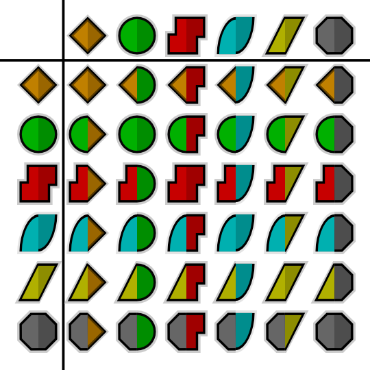
In the chart above the In interpolation is shown on the left, and
the Out interpolation is shown across the top.
Note: the .sif file used to generate these screenshots is available.
Here is an
Interpolation.sif
showing 25 different blobs, and how
they move with different combinations of Waypoints. It renders to a
634K .avi
file, and is
available in lower resolution on
YouTube. Notice how:
the blobs with any red (Constant) on them don’t move at all
the yellow (Linear) sides of blobs ‘bounce’ off the walls
the cyan (Ease) sides slow gracefully to a halt at the walls
the green (TCB) sides bounce at the top (the animation is a single down-and-up animation, looped, so there’s no ‘context’ at the top for the TCB to fit the curve to) but act smoothly at the bottom
The ‘undefined’ (grey) symbol is used when the row in the Timetrack Panel represents multiple Waypoints. For example, the ‘vertices’ row represents all the vertices making up a Spline. Each of those vertices can have multiple Waypoints, each with different interpolations. If all the interpolations are the same, that interpolation’s symbol will be used. Otherwise, the grey ‘undefined’ symbol is used.
Look at the Waypoints below. They are from the Timetrack for the
Vertices of an Outline Layer.

You’ll see the left side of each of the Waypoints is colored. This means
the In interpolation for each vertex is the same. However, the right
side is grey, indicating that the Out interpolation for each vertex
differs.
TODO: rewrite the above so it doesn’t hurt the brain so much.
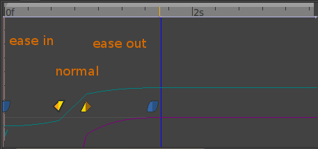
Example combining Waypoints
Ease in - Normal - Ease out